An RMU can remain enclosed and apparently serviceable while its cable terminations, interlocks, operating mechanism or protection functions deteriorate. By the end, you will know what a proper maintenance programme examines, which tests to request, how to set inspection intervals and when an alarm or defect requires qualified investigation before re-energisation.
Key takeaways
- Inspect cable terminations, earthing switches, fuses, and enclosure condition.
- Follow a documented isolation, proving-dead, earthing, inspection, and testing sequence.
- Set intervals according to RMU technology, duty, environment, and manufacturer instructions.
- Record test results, defects, corrective actions, and equipment identification details.
What an RMU Does—and What Preventive Maintenance Finds
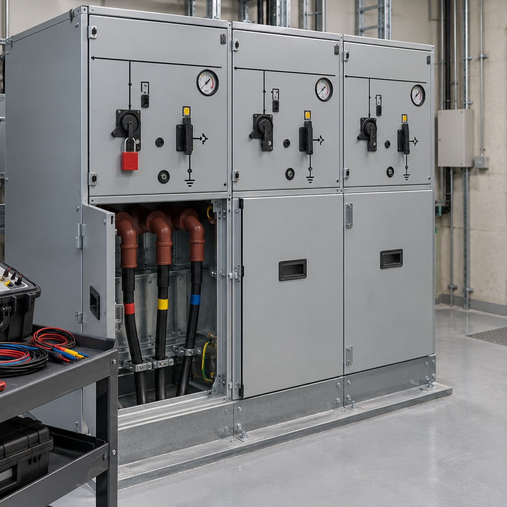
A ring main unit is a compact medium-voltage switchgear assembly that connects incoming and outgoing feeders while allowing a transformer or other load to be isolated. Its operating system includes the enclosure, busbars, load-break switches, circuit breakers, fuses, earthing switch, cable compartments and cable terminations—not just the primary tank.
A sealed enclosure does not make the rest of the RMU maintenance-free. Moisture, contamination, poor screen bonding, loose connections, damaged seals, stiff mechanisms or failed interlocks can create heating, partial discharge or an unsafe switching sequence while the enclosure still appears intact.
RMU preventive maintenance finds deterioration before it causes a fault or trip. Corrective repair starts after a defect, trip or failure has already interrupted service. Use this distinction:
- Preventive maintenance examines condition, tests insulation and contact resistance where specified, checks protection response, and proves interlock operation before failure.
- Corrective repair restores a failed component after evidence such as a trip, burn mark, abnormal temperature or damaged termination.
- A visual inspection finds cracks, corrosion, contamination, leakage evidence or discoloration, but it cannot prove insulation condition, contact resistance, protection response or interlock operation.
Circuit breaker maintenance therefore belongs within the complete RMU scope, alongside switch, fuse, earthing, termination and control checks. A work order marked “inspected” is not evidence that the equipment remains electrically sound.
The RMU Components and Technology That Set the Maintenance Scope
The maintenance scope changes with the insulation system, but every RMU requires more than a tank inspection. Technicians must examine the current path, switching mechanism, cable interfaces, protection and earthing system as one assembly.
| Insulation technology | Main inspection emphasis | Common consequence of neglect |
|---|---|---|
| SF6-insulated RMU | Gas-density indication, leakage evidence, terminations, mechanism and interlocks | Loss of insulation margin or failed switching |
| Vacuum-insulated switchgear | Vacuum interrupter condition, operating mechanism, contact wear and position feedback | Contact failure or an unsafe false position |
| Air-insulated switchgear | Busbar insulation, clearances, contamination, moisture and enclosure condition | Tracking, flashover or reduced insulation resistance |
A sealed-for-life SF6 switchgear unit does not normally need routine gas replenishment. Its density monitor, temperature context, leakage evidence, enclosure corrosion, operating mechanism, interlocks, cable terminations and earthing still require inspection. A pressure value without ambient temperature or density-monitor status is an unreliable comparison between two units because gas pressure changes with temperature.
Use the following scope for the physical and functional inspection:
- Check busbars, cable-compartment seals, cable screens, stress-control parts and separable connectors for moisture, contamination, poor seating, heating and inadequate screen bonding.
- Examine fuse compartments, auxiliary contacts, locking arrangements, operating mechanisms, position indicators and interlocks; a stiff mechanism or false indication can defeat an otherwise sound switch.
- Verify enclosure corrosion, earthing and bonding, control wiring, auxiliary supply and protection-relay connections. Record operation count, alarm status and defects rather than closing the work order with “inspected.”
The Safe Inspection and Testing Sequence
No compartment should be opened and no device operated until the circuit is identified, isolated and proved safe. An RMU’s internal-arc rating does not permit energised maintenance; it does not replace the site switching and arc-flash procedure.
- Review the single-line diagram and OEM manual. Identify every source, backfeed, auxiliary supply and possible connection through transformers, generators or cables.
- Issue a permit to work, then isolate the RMU and apply lockout tagout to every isolation point. Record the equipment boundary.
- Prove the voltage tester on a known live source, test every relevant conductor for absence of voltage, then prove the tester again. This is proving dead, not merely checking an indicator.
- Discharge stored energy, release or block mechanical energy, and apply the specified earths before access or testing.
Request tests that answer a defined question:
| Test | What it proves | Control |
|---|---|---|
| Insulation-resistance testing | Insulation condition between conductors and earth | Use OEM voltage and disconnect or protect connected devices |
| Contact resistance | Resistance across closed contacts and joints | Compare phases and historical results |
| Breaker timing or travel | Opening, closing and mechanism movement | Apply where a circuit breaker and OEM limits require it |
| Relay secondary injection | Protection pickup, timing and trip logic | Isolate trip circuits as specified |
| Cable or sheath test | Cable insulation or sheath integrity | Perform only within the specified boundary |
| Earth continuity and interlocks | Bonding integrity and correct mechanical or electrical sequencing | Test every relevant path and position |
Test voltage, boundaries and pass/fail limits belong to the specific RMU. Disconnect or protect cables, transformers, surge arresters, voltage transformers and electronic devices exactly as the OEM procedure requires. Record the instrument, method and limits with each result.
How to Set the Interval and Respond to Warning Signs
Set the RMU inspection interval from risk, not from a calendar alone. A fixed annual service is insufficient because duty and exposure change. Use the manufacturer’s instructions, switching frequency, mechanical operation count, fault and trip history, indoor or outdoor location, humidity, dust, salt pollution, load criticality, accessibility and previous thermography findings.
1. Review the duty and environment against the OEM limit. A lightly operated indoor unit may need a different interval from an outdoor RMU exposed to moisture, dust or coastal salt. Increase scrutiny after a fault, unexplained trip or major load change.
2. Use thermal imaging under meaningful load. Compare phases and record load, ambient temperature and test conditions; a low-load survey can miss a high-resistance lug or connector. Use partial discharge testing with the same method, sensor positions and operating conditions each time, because background noise and sensor placement can distort an isolated result.
3. Treat partial-discharge noise or smell, abnormal heating, discoloration, tracking, corrosion, a low SF6 pressure alarm, failed interlock, stiff operation, moisture ingress, cracked insulation and unexplained protection trips as urgent findings. Stop and investigate; do not create extra operations merely to test a mechanism.
4. Follow the OEM limit and site electrical safety procedure to decide whether the RMU remains out of service. Never bypass protection or interlocks. When comparing an electrical contractor such as Navyashree Engineers Private Limited, ask for the proposed scope, test boundaries, return-to-service authority and defect-escalation process.
The Standards and Records That Make Maintenance Defensible
An RMU maintenance file is defensible only when it connects the work to named standards, the OEM manual and repeatable evidence. Use the OEM maintenance manual with IEC 62271-200 for AC metal-enclosed switchgear, IEC 62271-103 for switches, IEC 62271-100 for circuit breakers, and IEC 62271-102 for disconnectors and earthing switches.
1. Record the asset identity, rating, operation count, fuse and protection details, gas-density or pressure indication, alarm status and ambient conditions. A pressure value without temperature context is a poor comparison between inspections.
2. Identify the test instrument, calibration status, method and test boundaries. Preserve insulation-resistance and contact-resistance results, breaker timing or travel data, relay secondary-injection results, cable or sheath-test details, earth-continuity results and interlock-operation results.
3. Attach thermal and partial-discharge findings, including the measurement method and location. Record cable-termination work, defects deferred, corrective actions, and the name and role of the person authorising return to service.
Compare each new result with the baseline. A rising contact resistance, worsening thermal pattern or changing partial-discharge signal reveals gradual deterioration better than a work order marked “complete.”
NFPA 70B:2023 can support a documented electrical-equipment maintenance programme. It does not replace OEM limits, equipment-specific test procedures or the qualified-person procedure required for safe work.
Frequently asked questions
What does RMU preventive maintenance inspect?
It covers the enclosure, busbars, load-break switches, circuit breakers, fuses, earthing switch, cable compartments, and cable terminations.
Why does RMU technology affect the maintenance scope?
Air-insulated, gas-insulated, and solid-insulated RMUs have different access points, failure modes, testing needs, and manufacturer instructions.
What is the safe sequence for RMU maintenance?
Isolate the circuit, apply the approved lockout procedure, prove the conductors dead, apply earths, inspect, test, restore, and document the work.
How should you choose an RMU maintenance interval?
Use the manufacturer’s schedule, RMU technology, operating duty, site environment, inspection findings, and past test results.