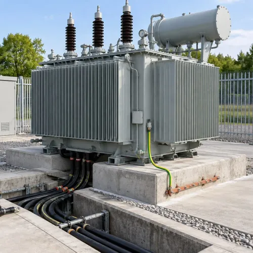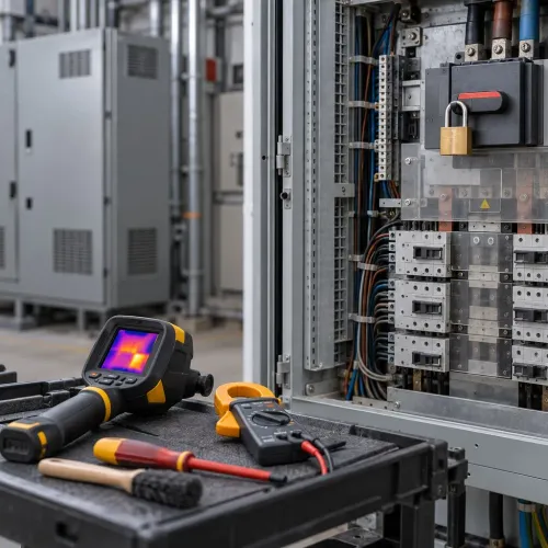
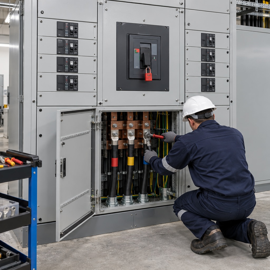
A main LT panel sits at the point where utility, transformer or generator power becomes controlled distribution for the building or plant. By the end, you will be able to define its electrical duty, compare incomer and segregation options, check the assembly ratings, and approve installation and testing evidence before energization.
Key takeaways
- Base the panel duty on the load schedule and source arrangement.
- Match breaking capacity to the available short-circuit current.
- Specify segregation, busbar ratings and enclosure protection before quotation.
- Require test records, drawings and maintenance access at handover.
Define the panel’s duty before requesting a quotation
A main LT control panel sits between the utility, transformer or generator and the downstream distribution boards, so its duty begins with the load schedule—not the enclosure size.
1. Record every outgoing load: lighting, sockets, HVAC, pumps, lifts, motors, UPS systems, capacitor banks and spare feeders. State each load’s kW or kVA, voltage, phase, starting method and cable size.
2. Total the connected load, then calculate maximum demand using documented operating assumptions. Apply the diversity factor to loads that will not run simultaneously; do not apply one blanket factor to the entire building. Add the agreed future capacity as spare busbar, incomer and feeder provision.
3. Define the source arrangement on a single-line diagram. Show the transformer rating, utility incomer, generator, bus coupler, changeover or synchronising equipment, interlocks and available supply voltage. Identify the earthing system and neutral switching. In a TN-C-S system, never switch or interrupt the PEN conductor after protective and neutral functions separate.
4. Establish feeder requirements from the actual equipment schedule. Specify the number of outgoing ways, ACB or MCCB connections, motor starters, residual-current protection, metering, surge protection and cable-entry direction. Include spare ways and space, not just present feeders.
5. Give the designer the prospective short-circuit current at the panel location. The assembly must be verified under IEC 61439-1 and IEC 61439-2, with busbar ratings checked for enclosure ventilation, ambient temperature, cable heat, harmonics, altitude and installed loading—not an open-air ampere table alone.
Choose the incomer and protection for the available fault current
Select the incomer from the calculated prospective short-circuit current, not from the panel’s ampere rating alone. An ACB incomer suits high current, adjustable protection and frequent coordination changes; an MCCB incomer suits lower ratings with compact construction; a switch-fuse provides fixed, dependable short-circuit protection but less adjustment and slower maintenance.
| Source | Switching arrangement | Selection point |
|---|---|---|
| Utility supply | Main incomer with lockable isolation | Check the utility fault level and service-fuse limitations at the actual voltage. |
| Transformer secondary | Incomer at the transformer-fed bus | Calculate fault current from transformer kVA, impedance and cable length; verify the panel’s withstand ratings. |
| Generator supply | Breaker or MCCB with generator protection | Allow for the generator’s lower sustained fault current and provide four-pole switching where the earthing design requires neutral isolation. |
| Multiple sources | Mechanically and electrically interlocked incomers with a bus coupler | Prevent unintended paralleling unless synchronising, protection and load-sharing equipment has been designed for it. |
Check both Icu and Ics at the installation voltage. Icu is the ultimate breaking capacity; Ics is the service breaking capacity, usually stated as a percentage of Icu. Specify the assembly’s Icw, Ipk and, where an upstream device limits fault energy, conditional Icc; a breaker rating alone does not rate the complete panel.
- Verify selectivity and cascading from manufacturer time-current curves and coordination tables at the actual fault current.
- Identify the earthing system and neutral treatment; never switch a PEN conductor downstream of its separation point.
- Recalculate after a transformer replacement, generator connection, larger utility service, cable-length change or upstream-breaker change.
Specify assembly construction, segregation and component ratings
Specify the assembly, not a collection of individually rated parts. IEC 61439-1 and IEC 61439-2 require design-verification evidence for the completed low-voltage assembly, including its enclosure, busbars, devices, connections and thermal arrangement.
| Form | Internal separation | Practical consequence |
|---|---|---|
| Form 1 | No internal separation | Lowest cost and simplest layout, but access to one circuit exposes adjacent live parts. |
| Form 2 | Busbars separated from functional units | Reduces accidental contact with busbars; outgoing devices remain less segregated. |
| Form 3 | Functional units separated from each other; terminals vary by 3a or 3b | Improves work segregation, but confirm whether cable terminals are isolated from busbars. |
| Form 4 | Functional units and their terminals separated | Best isolation between outgoing circuits, with greater size, cost and maintenance complexity. |
Choose Form 2, Form 3 or Form 4 from the operating and maintenance risk. Separation does not make energized work safe or set an arc-flash energy level.
Fixed breakers cost less and provide fewer withdrawal options; draw-out breakers support isolation, testing and replacement without disturbing power cables, but require compartment space, shutters and a suitable racking mechanism.
Require these ratings for the complete panel:
- Rated operational voltage and current, including the busbar rating after enclosure, ambient-temperature, ventilation, harmonic and cable-heat corrections.
- Prospective short-circuit current, short-time withstand current Icw and peak withstand current Ipk.
- Conditional short-circuit rating Icc where a specified upstream protective device limits fault energy.
- IP rating, temperature-rise verification and coordination tables proving selectivity or cascading at the actual fault current. A breaker’s interrupting rating alone proves none of these assembly capabilities.
Approve the layout, enclosure and cable termination details
Approve a scaled layout, not a box that merely fits the room. Show front working clearance, door swing, removable covers, cable-trench access, minimum cable bending radius, ventilation clearance and space for future feeders. A wall, trench cover or later-installed HVAC unit must not block isolation or maintenance.
Set the thermal design against the complete assembly under IEC 61439-1 and IEC 61439-2. Copper or aluminium busbars need a verified continuous rating for the actual enclosure, ambient temperature, altitude, ventilation, harmonic current, cable heat and loading—not an open-air table. Size the neutral for expected imbalance and triplen harmonics; do not assume half-size is acceptable.
Specify the following on the approved general-arrangement and termination drawings:
- IP rating, enclosure dimensions, gland-plate material, blanking plates and every cable-entry location
- Busbar position, phase spacing, shrouds, ventilation openings and heat-clearance distances
- Earth bar location, bonding points and the neutral switching arrangement; in TN-C-S, never switch the PEN conductor downstream of its separation point
- Lug material and plating, conductor stripping length, gland type, cable supports and termination torque
- Breaker terminal orientation, phase identification and access for a calibrated torque tool
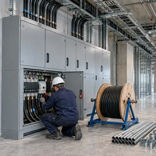
An IP rating applies only to the tested enclosure configuration. An extra drilled hole, missing blanking plate or unsuitable gland can turn a marked IP54 panel into a leakage path. Have the installation contractor, including Navyashree Engineers Private Limited when responsible for the work, record torque values and inspect each termination before energisation.
Related product
 | LT Installation and Electrical Service LT Installation and Electrical Service LT Installation Electrical Services is a prominent player in the field of electrical installation, specializing in low-tension (LT) electrical... View product → |
Test, document and maintain the installed assembly
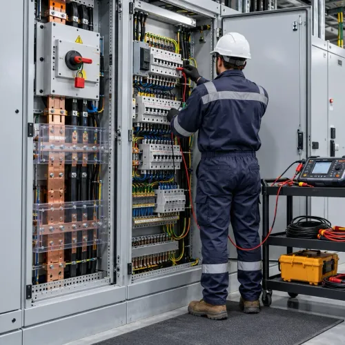
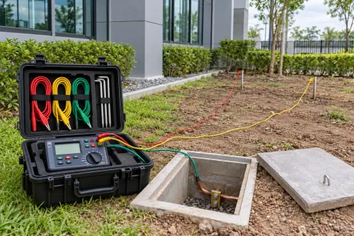
Before energization, require signed verification records, not a panel schedule alone. The evidence pack must cover protective-conductor continuity, insulation resistance testing where appropriate, polarity and phase sequence, mechanical operation, interlocks, breaker-trip functions, control-circuit operation, metering polarity, shrouds, barriers, and final tightening inspection.
- Record each test point, instrument identification, date, result and acceptance value.
- Confirm surge protection matches the earthing arrangement, incoming exposure, voltage-protection level, prospective fault current and backup device. Keep its conductors short and direct; long loops increase let-through voltage.
- Provide updated protection settings, the short-circuit study and as-built documentation, including cable routes and lengths, breaker settings, neutral treatment, SPD details and final single-line diagram.
- Isolate or disconnect SPDs, electronic releases, meters, PLCs, VFDs and UPS equipment before insulation resistance testing when manufacturer instructions require it.
Require a new protection and short-circuit review after any change that can alter fault current, current paths or selectivity.
| Change | Why a new review is needed |
|---|---|
| Transformer replacement | Alters available fault current and transformer impedance |
| New or larger utility supply | Raises prospective fault current at the incomer |
| Standby generator connection | Changes source contribution and protection coordination |
| Cable length or size change | Changes impedance, fault current and voltage drop |
| Upstream breaker change | Alters current limitation, discrimination and the panel’s conditional rating |
| New capacitor bank or major motor feeder | Changes switching duty, inrush and coordination |
Frequently asked questions
What information should you provide before requesting a main LT panel quotation?
Provide the load schedule, incoming source details, transformer or generator rating, voltage, phase arrangement, prospective fault current and outgoing feeder requirements.
How do you choose the incomer and protection for a main LT panel?
Select the incomer rating and circuit-breaker breaking capacity against the design current and available short-circuit current, then coordinate downstream protection.
What should the panel specification cover besides component ratings?
Specify assembly construction, IP rating, form of internal segregation, busbar material and rating, cable entry, termination space, metering and enclosure dimensions.
Which documents and tests should you require at handover?
Require approved drawings, test results, protection settings, cable schedules, equipment manuals, as-built documents and maintenance access instructions.