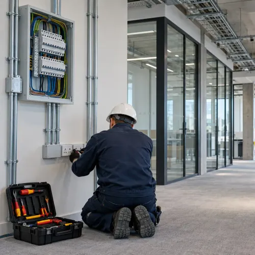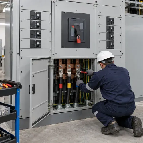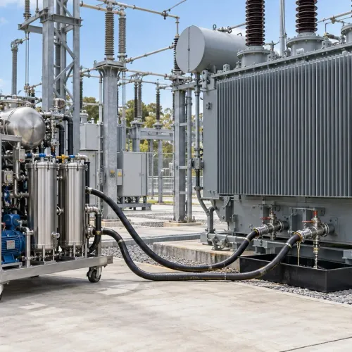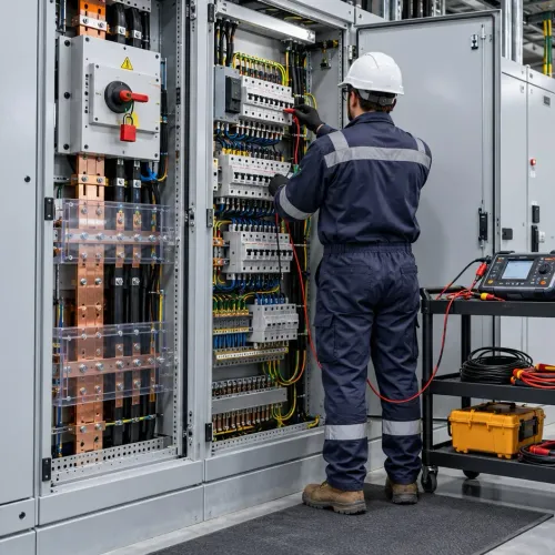
Choosing an electrical supply is not just a question of adding equipment ratings. You need a defensible demand forecast, a utility-ready design package, coordinated protection, and commissioning records that remain useful when the facility expands. By the end, you can map the project from the first load estimate through energisation, handover and maintenance.
Key takeaways
- Match supply voltage to peak demand, sensitive equipment and planned expansion.
- Build the load schedule from connected loads, demand factors and operating scenarios.
- Compare transformer quantity and capacity against redundancy, maintenance and future-load needs.
- Submit coordinated drawings, calculations and protection details before utility approval.
Decide the Supply Strategy Before Designing the Substation
A sanctioned load does not by itself decide the supply arrangement. Match the facility’s maximum demand, voltage-sensitive equipment, expansion plan and utility rules to the available utility voltage before drawing the substation.
1. Gather the utility and project inputs: sanctioned load, connected load, forecast maximum demand, operating hours, motor-starting loads, HVAC capacity, tariff category, future expansion and available utility voltage.
Ask the utility to confirm the point of supply, fault level, metering location, CT/PT ratios and accuracy class, protection interface, transformer ownership, inspection access, earthing and sealing requirements.
2. Prepare a preliminary short-circuit and voltage-drop study. Check the HT bus, transformer secondary and major LT boards under maximum and minimum fault conditions. A supply that appears adequate in kW can still cause motor-start voltage dips, excessive fault duty or poor transformer loading.
3. Compare the options with the utility’s approved scheme:
| Option | Choose it when | Main consequence |
|---|---|---|
| LT supply | Demand is modest and the utility offers adequate low voltage | No onsite transformer, but larger incoming currents and greater voltage-drop exposure |
| HT connection | The facility has qualifying HT demand or HT-rated process equipment | Requires HT metering, protection, restricted access and utility coordination |
| HT intake with onsite transformer | The utility offers an 11 kV supply and the facility needs substantial LT distribution | Adds transformer, HT switchgear, earthing, maintenance and capital cost, but reduces LT incoming current and supports expansion |
Confirm the terminology with the utility: an HT connection often means an 11 kV supply terminating at a customer-owned transformer. Do not finalise the layout until the approved metering and protection drawings are available.
Build a Load Schedule That Predicts Demand
A realistic maximum-demand estimate starts with operating behaviour, not the total of every nameplate. Record each load’s rated kW or kVA, quantity, duty cycle, operating hours, starting method, expected running power factor and whether it operates continuously, intermittently or only during emergencies.
Build the schedule by load group:
- Lighting: installed wattage, controls and occupied-area hours.
- Socket outlets: connected rating, occupancy allowance and diversity.
- HVAC: chiller, pump, fan and heat-rejection loads, including seasonal operation.
- Lifts, pumps and fire systems: duty, standby and starting sequence.
- UPS, data-centre, process and converter loads: actual demand, battery charging and harmonic content.
- Spare and future capacity: identify it separately instead of hiding it in present demand.
For each item, calculate expected running kW as connected load multiplied by its utilization factor. Add the individual maximum demands, then apply a documented diversity factor: coincident maximum demand equals the sum of individual maximum demands divided by the diversity factor.
Use operating schedules and measured data where available; do not apply one blanket factor to the whole facility.
Convert coincident kW to kVA using the running power factor. Account for power factor correction at the point where it will operate, because correction reduces upstream kVA but not the equipment’s kW. Check motor-starting current and the worst simultaneous starts separately for voltage dip, and flag UPS, variable-speed drives and LED loads for harmonic heating.
Add a clearly labelled growth allowance after calculating present maximum demand.
Choose Transformer Capacity, Quantity and Incoming Voltage
Size transformer capacity from the coincident maximum-demand profile, not the sum of nameplate ratings. Add motor-starting voltage-drop checks, nonlinear-load harmonic heating, ambient temperature, ventilation, and a documented forecast of loads expected during the design life.
Reserve only the quantified growth allowance; a blanket oversize leaves the transformer lightly loaded and wastes energy through poor partial-load efficiency.
| Arrangement | Benefit | Main check |
|---|---|---|
| One transformer | Lowest capital cost and simple protection | No supply redundancy; one failure can stop the facility |
| Two transformers in parallel | Redundancy and staged capacity for growth | Match voltage ratio, vector group, phase sequence, polarity, impedance and ratings |
| Two separate transformers | Independent buses and easier maintenance | Transfer scheme, protection coordination and space for separate equipment |
Choose transformer impedance with the short-circuit study. Lower transformer impedance improves voltage regulation and motor-starting performance, but raises prospective fault current; higher impedance limits fault current but increases voltage drop. Confirm the selected value against every breaker’s interrupting and short-time withstand rating.
Use parallel units only after checking load sharing at normal and emergency configurations. A small unit operating alone during low demand can improve partial-load efficiency, while the remaining unit provides redundancy and maintenance flexibility.
Confirm the incoming voltage with the utility’s point-of-supply approval, available fault level, metering position, CT and PT ratios, protection interface, transformer ownership and inspection access. The sanctioned load alone does not settle these decisions. Leave physical space, cable routes and switchgear provisions for the approved future capacity, rather than installing unused transformer kVA today.
Turn the Design into a Utility-Ready Engineering Package
Procurement should wait until the utility interface, site constraints and protection calculations are frozen. Confirm the point of supply, incoming voltage, utility fault level, metering location, transformer ownership, inspection access, earthing arrangement and sealing requirements with the distribution utility.
Complete these investigations and design records:
- Survey the plot, existing services, cable routes, transformer access, equipment clearances and drainage.
- Measure soil thermal resistivity for buried cables and earth resistance at proposed electrode locations.
- Issue the load schedule, cable schedule, equipment specifications, earthing and lightning-protection drawings, control schematics and an approved single-line diagram.
- Complete a short-circuit study for the HT bus, transformer secondary, major LT boards and relevant downstream boards, using maximum and minimum fault cases.
- Complete a protection coordination study covering utility protection, transformer inrush, motor starting, CT saturation and relay settings.
- State CT and PT ratios and accuracy class, burden, polarity, knee-point capability where required, secondary wiring, test links and shorting facilities in the metering and protection design.
| Package item | What to verify | Failure if omitted |
|---|---|---|
| Utility interface | Fault level, metering scheme and seals | Late panel or layout changes |
| Cable design | Derating, voltage drop and short-circuit withstand | Overheating or motor-starting voltage loss |
| Switchgear duty | Interrupting and short-time withstand ratings | Breaker cannot safely clear a fault |
| Protection file | Curves, settings and operating configurations | Upstream trip or loss of selectivity |
Navyashree Engineers Private Limited can add practical value by checking that drawings match installation access, termination details and commissioning realities before materials are ordered, rather than discovering those conflicts during energisation.
Related products
 | HT Installation and Electrical Service HT Installation and Electrical Service Navyashree Engineers team does the installation, testing & commissioning of overhead HT/ LT transmission lines. View product → |
 | LT Installation and Electrical Service LT Installation and Electrical Service LT Installation Electrical Services is a prominent player in the field of electrical installation, specializing in low-tension (LT) electrical... View product → |
Control Energisation, Handover and Future Changes
A breaker that closes without verified protection is not a commissioned installation. Energise only after documented commissioning tests confirm the equipment, wiring and protection scheme under the approved operating configuration.
| Stage | Evidence to review | Release decision |
|---|---|---|
| Pre-energisation | Cable continuity, phasing, insulation resistance, specified withstand tests, transformer ratio and vector group, breaker timing and contact resistance | Correct defects before applying voltage |
| Protection proving | CT polarity, excitation and shorting facilities; relay secondary injection; trip-circuit supervision, intertrip and interlock tests | Confirm each trip command reaches the correct breaker |
| System proving | Earth-grid continuity, touch and step-voltage assessment, earthing and lightning protection bonds, automatic-transfer and emergency-power sequences | Approve the energisation sequence and emergency response |
Treat handover as a controlled record, not a bundle of certificates. Require:
- An as-built single-line diagram, load schedule and cable schedule showing final ratings, routes and circuit identifiers.
- Protection settings, coordination-study revision, relay event records and equipment test certificates.
- CT and PT ratios, accuracy classes, burden details, metering scheme approval and sealed secondary wiring; never leave an energised CT secondary open.
- Torque records, earthing results, operating procedures and maintenance intervals.
Assign an authorised person to control switching, access, isolation, lockout and permit-to-work activities. Record every setting change and inspection.
Before adding a generator, solar inverter, UPS or large drive, recalculate fault current, reverse-power behaviour, neutral current, protection coordination and breaker duty. Update drawings, studies and settings before connection; undocumented expansion can invalidate the original design.
Frequently asked questions
What should you decide before designing an HT or LT substation?
Decide the supply strategy from maximum demand, voltage-sensitive equipment, expansion plans and the utility’s available voltage and rules.
How do you build a load schedule that predicts demand?
List each connected load, operating condition and demand factor, then test the total against realistic peak-use scenarios.
How should you choose transformer capacity and quantity?
Compare required capacity with redundancy, maintenance access, operating flexibility, incoming voltage and the facility’s future load.
What belongs in a utility-ready electrical engineering package?
Include coordinated single-line diagrams, load calculations, equipment ratings, protection details, layouts and the documents required for utility review.
How do you control energisation, handover and future electrical changes?
Use an approved energisation sequence, test records, as-built drawings, operating instructions and a controlled process for later modifications.
Related products
 | Commercial Electrical Contractors Commercial Electrical Contractors Navyashree Engineers, is a professionally managed class 1 Electrical contractors in South india. View product → |
 | Electrical Design Consultants Navyashree Engineers provides high quality electrical system design & engineering capability, electrical project consultancy and construction... View product → |
 | Industrial Electrical Contractor Industrial Electrical Contractor Navyashree Engineers regards quality as its lifeline, customer’s demand as its motivation, innovation and transformation as part of the development... View product → |
 | Facility Management Services Navyashree Engineers. provides Facility Management Services to a large number of Corporates backed by Skilled & Technical manpower. View product → |