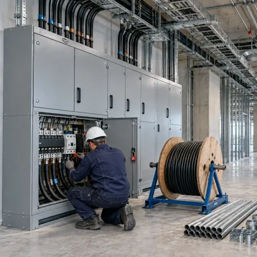
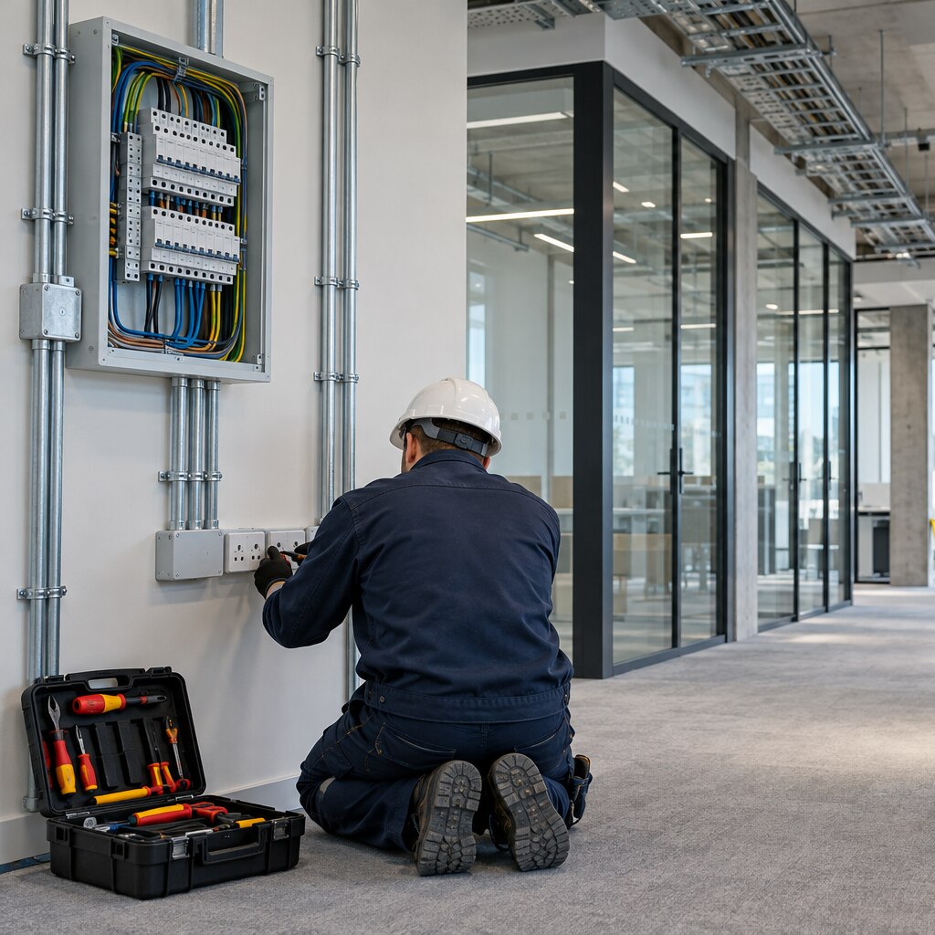
A commercial building’s internal electrical installation is more than cables and light fittings: it is the fixed low-voltage system that carries power from the main intake through panels, containment, final circuits and connected equipment. By the end, you will be able to map the scope room by room, separate it from utility and specialist work, and check whether the proposed design, testing and handover documents are complete.
Key takeaways
- Start the scope at the service termination, meter position or main isolator.
- Use distribution boards, protective devices and labelled circuits to reach each load safely.
- Verify insulation resistance, continuity, polarity, earthing and functional tests before energisation.
- Make drawings, test certificates, schedules and as-built records part of handover.
Where the Internal Installation Starts and What It Covers
Commercial internal electrical installation starts at the point where the incoming supply is handed over to the building’s electrical system, usually at the service termination, meter position or main isolator. It then covers the fixed low-voltage equipment that distributes and uses power inside the premises.
- Main LT panel, incomer, busbars, metering arrangements and protective devices
- Sub-main distribution boards, busbar trunking, feeders and local isolators
- Cable trays, ladders, conduits, trunking, junction boxes and other containment
- Final circuits serving lighting, socket outlets, HVAC, pumps, lifts, machinery and other fixed equipment
- Earthing electrodes where specified, main protective bonding and circuit protective conductors
- Control wiring, emergency supplies and connections to specialist systems where the contract includes them
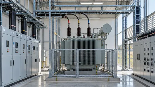
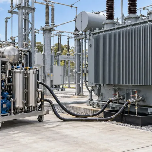
The boundary is contractual as well as physical. A transformer or HT switchgear located on the property does not automatically form part of the internal LT installation; ownership, voltage level and the employer’s scope decide the division.
| Scope area | Usually includes | Usually outside the internal scope |
|---|---|---|
| Utility side | Overhead lines, utility transformer, utility substation and upstream service network | Building final circuits |
| Service interface | Service cable termination, meter position and agreed main isolator | Utility-owned meter or upstream equipment unless assigned |
| Building interior | Main LT panel, distribution, containment, wiring and fixed loads | Portable appliances, telecoms and specialist systems unless expressly included |
Initial verification belongs to the installation scope. Require inspection, continuity, insulation-resistance, polarity, earth-fault and protective-device test results, not only an installation certificate. Seal every fire-rated penetration with an identified tested system and record its location.
How Power Reaches Every Room and Equipment Point
Power enters the building at the main LT panel, where incoming protection, metering, switching and fault protection divide the supply into sub-main feeders. Those feeders run through cable trays, trunking, conduits or busbar systems to distribution boards serving each floor, zone or tenant area.
From each distribution board, final circuits carry power to individual rooms and equipment points. A room-by-room checklist should identify:
- Lighting circuits and controls: luminaires, switches, occupancy sensors, dimmers, daylight controls and control cabling, with emergency lighting treated as a separately designed life-safety system.
- Socket outlets: general-purpose outlets, dedicated outlets for workstations, cleaning equipment and specialist appliances, with circuit identification and protective-device coordination.
- Fixed equipment supplies: air-conditioning units, pumps, water heaters, kitchen equipment and machinery, each sized for its nameplate load and connected through a local isolator where safe maintenance requires it.
- Distribution and containment: circuit cables, junction boxes, access panels, cable supports, fire stopping and spare capacity for future additions.
- Protection and earthing: circuit breakers or residual-current protection where required, circuit protective conductors, main bonding and continuity connections back to the earthing arrangement.
- Interfaces: power, containment and isolators for fire alarm, security, access control, BMS, UPS or standby systems, while specialist design and commissioning remain separate unless included in the contract.
The installation is incomplete until each circuit is labelled, inspected and tested. Recorded continuity, insulation resistance, polarity, earth-fault performance and protective-device results belong in the handover file.
The Installation Sequence from Design to Energisation
Begin with a load schedule, not a cable size. Record each lighting, socket, HVAC, lift, process and fixed-equipment load as connected load, apply diversity to calculate maximum demand, and retain spare capacity for planned expansion.
1. Prepare the load assessment and single-line diagram. Show the incoming supply, main LT panel, sub-main distribution boards, busbars, protective devices, isolators, earthing arrangement and final circuits.
2. Coordinate each circuit for design current, cable rating, voltage drop, prospective fault current, disconnection time, thermal withstand and discrimination between protective devices. A design based only on normal load can cause nuisance trips or fault damage.
3. Set out routes and install trays, ladders, conduits, trunking and supports. Seal every penetration through a fire-resisting wall, floor or shaft with a tested or assessed fire-stopping system, and record its location; an unsealed later cable addition can invalidate the arrangement.
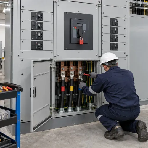
4. Install panels and containment, pull identified cables without exceeding bending or pulling limits, then terminate, gland, torque and label every conductor and circuit.
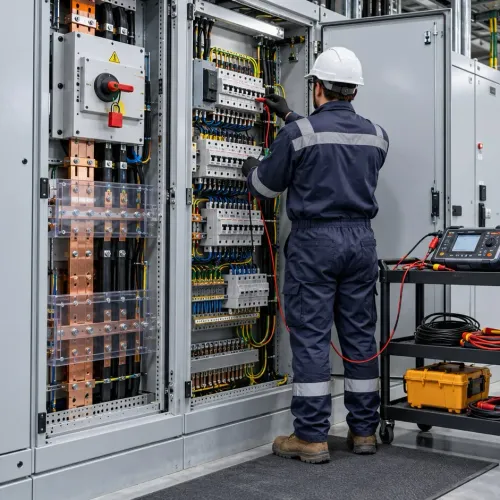
5. Inspect the completed work before energisation. Test continuity of protective conductors, insulation resistance, polarity, earth-fault loop impedance, prospective fault current and protective-device operation, recording results on the appropriate certificate and schedules.
6. Test emergency lighting as a life-safety system, including escape-route coverage, exit signs, autonomy, functional operation and records. Normal light fittings on a central battery do not replace this verification.
7. Energise in a controlled sequence, confirm phase identification and settings, and hand over marked-up drawings, distribution schedules, single-line diagrams, equipment data, warranties, spares, access details and an asset register aligned with the maintenance system.
How to Choose Conductors, Protection and Containment
Choose each conductor and protection device against design current, prospective fault current, installation environment and the next phase of expansion—not price alone.
| Option | Safety, capacity and access | Best comparison point |
|---|---|---|
| Copper versus aluminium conductors | Copper needs smaller terminations and resists installation damage; aluminium reduces weight and cost but needs correctly rated lugs, joint compound and torque control. | Compare current-carrying capacity, voltage drop, joint access and available spare ways. |
| XLPE and PVC insulation | XLPE tolerates higher conductor temperatures and suits heavily loaded submains; PVC is economical for ordinary final circuits but has a lower temperature limit. | Check ambient temperature, grouping, short-circuit withstand and fire-performance requirements. |
| MCB, MCCB and RCBO | An MCB protects a final circuit; an MCCB handles larger feeders and higher fault levels; an RCBO combines overcurrent and residual-current protection for individual circuits. | Verify breaking capacity, trip curve, selectivity and residual-current rating against the load. |
| Tray, ladder, trunking, conduit and underfloor systems | Tray and ladder provide accessible, ventilated routes; trunking and conduit improve segregation or mechanical protection; underfloor systems preserve floor access. | Check fill, bend radius, support spacing, heat dissipation, fire-compartment seals and spare capacity. |
Identify LED drivers, variable-speed drives, UPS units and IT supplies in the load schedule. Their harmonic currents can heat neutrals and cause nuisance trips, so assess neutral sizing and mitigation before selecting devices.
Inspect identification, supports, joints, protective-conductor continuity and fire stopping before ceilings or risers close. A packed route without accessible spare space turns the next circuit into demolition work.
How to Define the Contract Scope and Verify the Handover
Put every boundary in the contract before installation starts. State whether the electrical contractor supplies containment, power, isolators, fire-rated cables, controls wiring, testing and builders-work coordination, or only leaves connection points for a specialist.
| Interface | Electrical contract must state | Acceptance evidence |
|---|---|---|
| Fire alarm | Power supply, isolator, fire-rated cable, interface modules and testing responsibility | Specialist commissioning certificate and witnessed cause-and-effect test |
| Data cabling | Containment, segregation, outlets, pathways and cable ownership | Cable test results, labelling schedule and network contractor sign-off |
| Emergency lighting | Final circuits, fittings, central battery or self-contained units, autonomy test | Functional and duration test record |
| BMS, access control and security | Power, isolators, containment, dry contacts and programming boundary | Point-to-point test and integrated demonstration |
| Standby generator and UPS | Upstream supply, bypass, changeover, earthing and load-test responsibility | Load test, changeover test and equipment certificates |
Write exclusions explicitly: portable appliances, utility-owned equipment, telecoms networks, lifts, transformers, substations and external service connections remain outside the package unless priced and tested.
The scope must also identify the supply earthing arrangement, earthing and bonding, main protective bonds, circuit protective conductors and earth electrodes. Record continuity and fault-loop results. List every fire stopping penetration, the tested sealing system used and any restriction on later cable additions; containment alone does not seal a fire-rated wall.
Before handover, demand a signed package containing:
- Updated single-line diagrams, distribution schedules, circuit labels and protective-device settings
- Inspection and test certificates, energisation approval and specialist-system records
- Emergency-lighting duration results, fire-alarm interface tests and fire-stopping register
- Equipment manuals, warranties, spares, access details and an asset register
Navyashree Engineers Private Limited can help define these boundaries during design, but the contract must name the party responsible for each final certificate.
Related products
 | Commercial Electrical Contractors Commercial Electrical Contractors Navyashree Engineers, is a professionally managed class 1 Electrical contractors in South india. View product → |
 | Electrical Design Consultants Navyashree Engineers provides high quality electrical system design & engineering capability, electrical project consultancy and construction... View product → |
Frequently asked questions
Where does a commercial internal electrical installation start?
It starts at the incoming supply handover point, such as the service termination, meter position or main isolator, and covers fixed low-voltage systems inside the premises.
How does power reach every room and equipment point?
Power passes from the main switchboard through distribution boards, sub-circuits, containment and final connections to outlets, lighting, HVAC equipment and other defined loads.
What happens before a commercial electrical installation is energised?
The sequence includes design, approval, procurement, containment installation, cable pulling, termination, inspection, testing and correction of defects before energisation.
What should you verify at electrical installation handover?
Check approved drawings, single-line diagrams, cable schedules, circuit labels, test results, protection settings, as-built records, operation manuals and maintenance information.
Related products
 | LT Installation and Electrical Service LT Installation and Electrical Service LT Installation Electrical Services is a prominent player in the field of electrical installation, specializing in low-tension (LT) electrical... View product → |
 | Licensed Class 1 Electrical Contractor Licensed Class 1 Electrical Contractor Navyashree Engineers is a leading class 1 licensed electrical contractors in Bangalore. View product → |
 | Facility Management Services Navyashree Engineers. provides Facility Management Services to a large number of Corporates backed by Skilled & Technical manpower. View product → |